Tip of the Day 84: Scaling Injection Pressure on Analog Inputs
When working with electric machines the injection pressure must either come from a nozzle pressure sensor or from an electrical signal from the machine. We designed the eDART system and Lynx™ sensors to eliminate the need for all of the scaling steps described here. But if you need to use signals from another machine you are forced to tell the eDART how to set the scaling.
The electrical signal for pressure is usually 0 – 10V with a “low” voltage (not always zero) being no pressure and a “high” voltage (not always 10 V) being the highest pressure. Often we have no idea what voltage represents what pressure. The typical method is to assume that the full rated plastic pressure of the machine is the value at 10V. Alternatively we can try to get the scale value from the manufacturer. However these do not always work.
So here are some steps to adjust the scaling to match as needed. You should compare the machines reported hold pressure to the eDART’s to determine whether a scaling adjustment is necessary.
If you can do this at job startup:
- Start the job and stop at the sensor location screen
- Identify the serial number of the 0 – 10V input module ( “AI”, “Analog Input” ) that is wired to the machine’s injection pressure signal output.
- With the pressure off (usually motor off or machine in standby) write down the voltage shown under the “Value” column on Sensor Locations.
- Set a known hold pressure and purge (inject) until the screw hits bottom.
- Record the machine’s actual pressure and at the same time record the voltage in the “Value” column on the analog input.
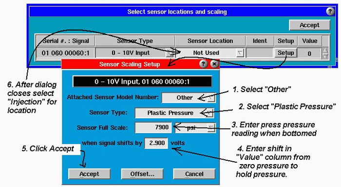
- Click the “Setup” button next to the analog sensor on Sensor Locations
- select “Other” for the model, select „Plastic Pressure“ for the type.
- Enter the change in pressure (should be just the hold pressure indicated on the machine) into the „Sensor Full Scale“ box
- Enter the change in voltage (high minus low) into the „when signal shifts by“ box.
- Accept the scaling dialog and Sensor Locations.
- After accepting “Sensor Locations” zero the injection pressure with the motor off or machine in standby.
Here is an example:
- The press controller was set to 8000 psi hold pressure
- The voltage read on the Sensor Locations = 0.2 (this is volts)
- The controller was purged to to bottom.
- The screen on the controller indicates 7900 psi pressure
- The Sensor Locations shows 3.1
- On the dialog box enter 7900 „full scale“ when the shift is 2.9 V (= 3.1 – 0.2).
- Click accept On the Sensor Locations screen select „Injection“ as the location of the plastic

If the job is already running:
- Again, remember to zero the injection pressure with the motor off or the press in standby.
- Check the eDART’s reporting of hold pressure by by using the cursor on the cycle graph over hold pressure or adding the Average Value / Stable Hold Pressure to Cycle Values.
- Record the machine’s reported hold pressure during hold.
- Compare the eDART’s hold pressure value to the machine’s hold pressure value during hold.
- Compute a multiplier by dividing the machine’s pressure reading during hold by the eDART’s stable hold pressure reading.

- Open sensor locations and click the “Setup” button for the 0 – 10 V Plastic Pressure / Injection input.
- Multiply the value already in the Sensor Full Scale box by the scale factor you computed above. Enter the result back into the „Sensor Full Scale“ box.
- Click accept on the scaling dialog and then again on Sensor Locations.
- Check to see if the hold pressures now match. They should.
In the above example let’s suppose that when we checked the hold pressure on the eDART with the cursor on the cycle graph it said 8100 psi during the flat, stable hold part of the cycle. But the press controller is indicating 8050 psi (actual) during hold. So dividing the two:

Multiply the „Sensor Full Scale Value“ by the multiplier to get the new sensor full scale value.


