
When these sensors are appropriate for an application, installation strategies, and which components help connect them back to the rest of an RJG® System.
Applies to: Auxiliary Hardware, Cables, Low Cavitation, Piezoelectric, Piezo, Button-Style, Testers, Installation Kits, Flush Mount, In-Cavity, Pressure Sensors
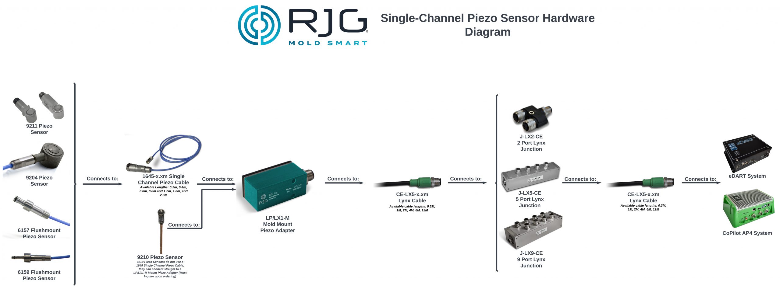
Required: 1645 Cable, LP/LX1-M signal conditioner, CE-LX5-XX Lynx® communication cable to report back to either an eDART® or CoPilot® System. If more than one sensor on the tool, junction will be required as well.
Warnings: The sensor heads are naturally heat rated up to 392°F (200°C). The signal conditioner boxes (LP/LX1-M) on the surface of the tool are only rated to 140°F (60°C). Design strategies to provide thermal isolation may be necessary if the tool is expected to run greater than 140°F, including low thermal conductive materials and/or risers with air gaps.
The piezoelectric sensor heads, their cables running through the tool, and the signal conditioner are all separate components with connections in between. These connection points can allow environmental factors to inhibit ideal sensor functionality: physical impediments (i.e. dirt, oil, humidity) or electrical noise can affect data integrity.
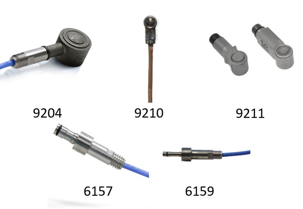
Single Channel Piezoelectric Sensors Options RJG Inc Currently Offers:
- Button Style
- 9204 Piezo Electric Force Transducer
- 0.49″ (12.6mm) Diameter – 392F (200C) Max Temperature Rating – 2,248lb Force Rating
- 9211 Piezo Electric Force Transducer
- 0.236″ (6.0mm) Diameter – 392F (200C) Max Temperature Rating – 562ln Force Rating
- 9210 Piezo Electric Force Transducer
- 0.138″ (3.5mm) Diameter – 392F (200c) Max Temperature Rating – 56lb Force Rating
- 9204 Piezo Electric Force Transducer
- Flush Mount Style
- 6157 Piezo Electric Flush Mount Force Transducer
- 0.157″ (4mm) Diameter – 392F (200C) Max Temperature Rating – 2000 BAR (29008 PSI) Rating
- 6159 Piezo Electric Flush Mount Force Transducer
- 0.098″ (2.5mm) Diameter – 392F (200C) Max Temperature Rating – 2000 BAR (29008 PSI) Rating
- 6157 Piezo Electric Flush Mount Force Transducer
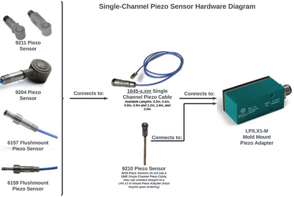
Except for the 9210, each of the Single Channel Piezoelectric Sensor is its own, individual component and requires a 1645 Cable to connect to the LP/LX1-M Signal Conditioner at the surface of the tool/mold. Unlike the others, the 9210 comes with the sensor head mated to the cable; then, like the others, that cable will also run to an LP/LX1-M signal conditioner at the surface of the tool.
The „button style“ sensor head is installed in the tool under an ejector pin, a transfer pin, or a static pin, with the cable running through a channel to the signal conditioner on the surface of the tool. „Flush mount“ sensor heads are installed so the flat of their tip helps create the cavity’s wall; then the cable runs through a channel to the signal conditioner on the surface of the tool.
Selecting the Appropriate Sensor for your Application
Whenever possible, RJG recommends using a button-style sensor over a flush mount sensor as these are less costly and less complicated to design, installation, and maintaining.
The flush mount sensors (6157, & 6159) are rated to 2,000 bar and can be installed wherever the part allows for a flat area and sufficient clearance from other tool geometries in the area. Note the limitations to machining the flush mount sensors‘ tips to match cavity walls.
The button-style sensors each have their own dimensions and full scale force ratings. Both of these factors come into play when selecting the appropriate model for an application–figures available in each model’s manual available for download on our website. For the safety and longevity of the sensor, RJG® recommends keeping the applications expected peak forces under 75% the sensor model’s full scale. For more on Sensor Selection, refer to our website here. You may also reach out to our Technical Support Department for further assistance.
We can determine the expected peak force (recommended for each sensor location in every instrumented tool) by taking the expected peak plastic pressure at the sensor’s pin location and multiplying that figure by the project surface area of the pin (on the cavity wall). This expected peak plastic pressure can be found from simulation, come from familiarity with similar processes, or estimated from the material’s tonnage factor found on its MSDS. (Material Safety Data Sheet)
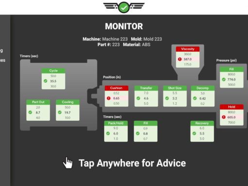
The RJG® eDART® and CoPilot® Systems receive the sensors‘ load data and converts it back from a raw force figure to the material’s pressure in the cavity using the pin surface area entered into the System (Note: be sure this pin information is entered correctly at Job Setup for the most accurate data).
Installing the Sensors in your Mold
Design guidance for the sensor head pockets, cable channels, and mounting associated equipment on the tool’s surface can be found in the product manuals under the Downloads tab on each sensor’s product page on our website.
When physically placing sensors into your tool, they should sit flush with the edge of the plate. You should be able to brush a flat edge across the pockets (safely) without catching them.
If the pin head is larger than the sensor set behind it, a counter bore should be present around the sensor head to allow the pin to press into the sensor freely, unobstructed by the surrounding steel.
Connecting the Single Channel Piezo Sensors on the Tool:
Each sensor head will require a 1645 Cable to connect and run through a channel in the mold to meet an LP/LX1-M Signal Conditioner on the surface of the tool. A Lynx® communication cable (CE-LX5-XX) is then used to connect with the rest of the larger, RJG® System–either into a junction box, or run back to the eDART® or CoPilot® System by the press. Please refer to Figure 2 for the Single-Channel Piezo Sensor Hardware Diagram.
Single-Channel Piezo Sensor Hardware Diagram with eDART System or CoPilot System