
[et_pb_section fb_built=“1″ admin_label=“section“ _builder_version=“4.16″ global_colors_info=“{}“][et_pb_row admin_label=“row“ _builder_version=“4.16″ background_size=“initial“ background_position=“top_left“ background_repeat=“repeat“ global_colors_info=“{}“][et_pb_column type=“4_4″ _builder_version=“4.16″ custom_padding=“|||“ global_colors_info=“{}“ custom_padding__hover=“|||“][et_pb_text admin_label=“Text“ _builder_version=“4.16″ background_size=“initial“ background_position=“top_left“ background_repeat=“repeat“ global_colors_info=“{}“]
The chart below is only a guide. In order to assure correct sensor selection for your application, we recommend contacting us directly.
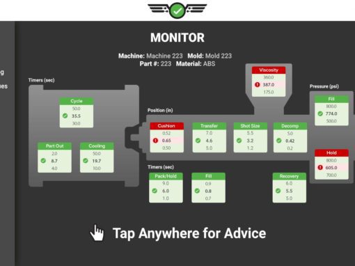
Select the Proper Sensor from the Table
- Locate the pin size that will be used and match it to the location on the part (Near the End of Fill or Near the Gate).
- The intersection of the row and column is the sensor to use (Lynx Strain Gage or Piezo based on the mold application).
Key
|
Normal Pressure, (e.g. Typical Molds, End of Cavity) 5000 PSI / 350 Bar / 35 MPa |
High Pressure (e.g. Thin Wall, Post Gate) 10,000 PSI / 700 Bar / 70 MPa |
|---|
 |
||||||||||||||
Lynx Strain Gage Button (Single Channel Only) |
||||||||||||||
| Pin Diameter (mm) | LS-B-127-50 | LS-B-127-125 | LS-B-127-500 | LS-B-127-2000 | LS-B-159-4000 | |||||||||
| 1.00 | ||||||||||||||
| 1.50 | ||||||||||||||
| 2.00 | ||||||||||||||
| 2.50 | ||||||||||||||
| 3.00 | ||||||||||||||
| 3.50 | ||||||||||||||
| 4.00 | ||||||||||||||
| 4.50 | ||||||||||||||
| 5.00 | ||||||||||||||
| 5.50 | ||||||||||||||
| 6.00 | ||||||||||||||
| 6.50 | ||||||||||||||
| 7.00 | ||||||||||||||
| 7.50 | ||||||||||||||
| 8.00 | ||||||||||||||
| 8.50 | ||||||||||||||
| 9.00 | ||||||||||||||
| 9.50 | ||||||||||||||
| 10.00 | ||||||||||||||
| 11.00 | ||||||||||||||
| 12.00 | ||||||||||||||
| 13.00 | ||||||||||||||
| 14.00 | ||||||||||||||
| 15.00 | ||||||||||||||
| 16.00 | ||||||||||||||
| 17.00 | ||||||||||||||
| 18.00 | ||||||||||||||
| 19.00 | ||||||||||||||
| 20.00 | ||||||||||||||
| 21.00 | ||||||||||||||
| 22.00 | ||||||||||||||
| 23.00 | ||||||||||||||
| 24.00 | ||||||||||||||
| 25.00 | ||||||||||||||
 |
||||||||||||||
Piezoelectric Button (Single or Multi-Channel) |
||||||||||||||
| Pin Diameter („) | 9210 | 9211 | 9204 | |||||||||||
| 1.00 | ||||||||||||||
| 1.50 | ||||||||||||||
| 2.00 | ||||||||||||||
| 2.50 | ||||||||||||||
| 3.00 | ||||||||||||||
| 3.50 | ||||||||||||||
| 4.00 | ||||||||||||||
| 4.50 | ||||||||||||||
| 5.00 | ||||||||||||||
| 5.50 | ||||||||||||||
| 6.00 | ||||||||||||||
| 6.50 | ||||||||||||||
| 7.00 | ||||||||||||||
| 7.50 | ||||||||||||||
| 8.00 | ||||||||||||||
| 8.50 | ||||||||||||||
| 9.00 | ||||||||||||||
| 9.50 | ||||||||||||||
| 10.00 | ||||||||||||||
| 11.00 | ||||||||||||||
| 12.00 | ||||||||||||||
| 13.00 | ||||||||||||||
| 14.00 | ||||||||||||||
| 15.00 | ||||||||||||||
| 16.00 | ||||||||||||||
| 17.00 | ||||||||||||||
| 18.00 | ||||||||||||||
| 19.00 | ||||||||||||||
| 20.00 | ||||||||||||||
| 21.00 | ||||||||||||||
| 22.00 | ||||||||||||||
| 23.00 | ||||||||||||||
| 24.00 | ||||||||||||||
| 25.00 | ||||||||||||||
 |
|||||||||||||||||
Multi-Channel Strain Gage Button (Multi-Channel Only) |
|||||||||||||||||
| Pin Diameter („) | MCSG-B-60-50 | MCSG-B-60-250 | MCSG-B-127-125 | MCSG-B-127-500 | MCSG-B-127-2000 | MCSG-B-159-4000 | |||||||||||
| 1.00 | |||||||||||||||||
| 1.50 | |||||||||||||||||
| 2.00 | |||||||||||||||||
| 2.50 | |||||||||||||||||
| 3.00 | |||||||||||||||||
| 3.50 | |||||||||||||||||
| 4.00 | |||||||||||||||||
| 4.50 | |||||||||||||||||
| 5.00 | |||||||||||||||||
| 5.50 | |||||||||||||||||
| 6.00 | |||||||||||||||||
| 6.50 | |||||||||||||||||
| 7.00 | |||||||||||||||||
| 7.50 | |||||||||||||||||
| 8.00 | |||||||||||||||||
| 8.50 | |||||||||||||||||
| 9.00 | |||||||||||||||||
| 9.50 | |||||||||||||||||
| 10.00 | |||||||||||||||||
| 11.00 | |||||||||||||||||
| 12.00 | |||||||||||||||||
| 13.00 | |||||||||||||||||
| 14.00 | |||||||||||||||||
| 15.00 | |||||||||||||||||
| 16.00 | |||||||||||||||||
| 17.00 | |||||||||||||||||
| 18.00 | |||||||||||||||||
| 19.00 | |||||||||||||||||
| 20.00 | |||||||||||||||||
| 21.00 | |||||||||||||||||
| 22.00 | |||||||||||||||||
| 23.00 | |||||||||||||||||
| 24.00 | |||||||||||||||||
| 25.00 | |||||||||||||||||
 |
||||||||||||||
Lynx Embedded Sensors (LES) |
||||||||||||||
| Pin Diameter (mm) | LES-B-127-50 | LES-B-127-125 | LES-B-127-500 | LES-B-127-2000 | LES-B-159-4000 | |||||||||
| 1.00 | ||||||||||||||
| 1.50 | ||||||||||||||
| 2.00 | ||||||||||||||
| 2.50 | ||||||||||||||
| 3.00 | ||||||||||||||
| 3.50 | ||||||||||||||
| 4.00 | ||||||||||||||
| 4.50 | ||||||||||||||
| 5.00 | ||||||||||||||
| 5.50 | ||||||||||||||
| 6.00 | ||||||||||||||
| 6.50 | ||||||||||||||
| 7.00 | ||||||||||||||
| 7.50 | ||||||||||||||
| 8.00 | ||||||||||||||
| 8.50 | ||||||||||||||
| 9.00 | ||||||||||||||
| 9.50 | ||||||||||||||
| 10.00 | ||||||||||||||
| 11.00 | ||||||||||||||
| 12.00 | ||||||||||||||
| 13.00 | ||||||||||||||
| 14.00 | ||||||||||||||
| 15.00 | ||||||||||||||
| 16.00 | ||||||||||||||
| 17.00 | ||||||||||||||
| 18.00 | ||||||||||||||
| 19.00 | ||||||||||||||
| 20.00 | ||||||||||||||
| 21.00 | ||||||||||||||
| 22.00 | ||||||||||||||
| 23.00 | ||||||||||||||
| 24.00 | ||||||||||||||
| 25.00 | ||||||||||||||
[/et_pb_text][/et_pb_column][/et_pb_row][/et_pb_section]